Commercial packaged rooftop units (RTUs) are self-contained mechanical systems combining refrigeration, air handling, gas/electric heating, and motorized economizer ventilation in a single weatherproof cabinet. When an RTU shuts down in lockout, field service technicians must isolate whether the fault originates in the 24VAC low-voltage safety string, microcomputer control logic, 3-phase high voltage distribution, or mechanical refrigeration loop.
Always open and lock out the external fused knife disconnect before opening electrical access panels. Commercial RTUs utilize 208V, 230V, 460V, or 575V 3-phase power capable of fatal arc-flash. Only certified technicians with true-RMS CAT-III 600V+ meters and NFPA 70E PPE should perform live electrical testing.
Section 1: Standard Sequence of Operations (DX Cooling Mode)
Understanding the normal baseline sequence of operations is the foundation of rapid fault isolation. On a standard two-stage commercial packaged RTU equipped with DDC or electromechanical controls, the sequence proceeds as follows:
- Thermostat / BAS Call: Building Automation System (BAS) or wall thermostat energizes terminal
G(continuous fan) andY1(Stage 1 Cooling). - Indoor Blower Startup: Blower contactor or VFD energizes. An air proving switch (differential pressure switch) closes across
P1-P2to verify airflow before compressor start. - Economizer Free-Cooling Evaluation: If equipped with an economizer and outdoor air temperature/enthalpy is below changeover setpoint (typically 55°F to 63°F), the modulating actuator drives open to 100% to provide free cooling. Compressor 1 remains locked out until economizer cannot satisfy space demand.
- Mechanical Stage 1 (Y1): If outdoor air is not suitable for economizer cooling, the control board checks the Circuit 1 safety string (High Pressure Switch, Low Pressure Switch, Freeze Stat, Compressor Internal Protector). If closed, anti-short cycle timer (typically 5 minutes) expires and Compressor Contactor 1 (M1) and Condenser Fan 1 energize.
- Mechanical Stage 2 (Y2): If space temperature continues to rise, terminal
Y2energizes. The control board closes Compressor Contactor 2 (M2) to bring Circuit 2 online.
Section 2: The 5-Step Systematic Troubleshooting Protocol
Step 1: 24VAC Control Circuit & Safety String Isolation
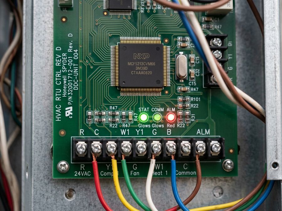
More than 60% of apparent "dead unit" calls stem from an open safety switch in the low-voltage control string. Do not assume the control board or microcomputer is defective without tracing voltage drops:
- Transformer Output: Measure voltage between
RandCon the low-voltage terminal strip. A healthy reading is between 24.0VAC and 28.5VAC. If voltage is 0VAC, check the 3.2A or 5A automotive blade fuse on the board. - Safety String Voltage Drop Test: Place the common meter lead on
C. With a call for cooling (Y1active), probe each terminal in sequence:- Inlet of High Pressure Switch (should read ~24VAC)
- Outlet of High Pressure Switch (if 0VAC, switch is tripped open on high head pressure)
- Inlet of Low Pressure Switch (should read ~24VAC)
- Outlet of Low Pressure Switch (if 0VAC, circuit is tripped on low refrigerant charge)
- Evaporator Freeze Stat (10k NTC thermistor or mechanical snap-disc)
Step 2: High Head Pressure Trip Diagnostics (Cutout: 550–600 PSIG R-410A)
When the microcomputer displays a 1-Flash High Pressure Lockout, head pressure exceeded the safety limit (typically 585–625 PSIG on R-410A commercial equipment):
- Condenser Airflow Restriction: Inspect coil face. Commercial RTU coils (especially multi-row or microchannel) trap cottonwood, dirt, and industrial soot between rows. Use an expanding foam coil cleaner rinsed from the inside out.
- Condenser Fan Motor Failures: Check if condenser fan blades spin freely. Measure motor run capacitor capacitance with a digital capacitance meter. Check motor winding resistance to ground (minimum 50 Megohms on 500VDC insulation test). If motor is failed or capacitor is weak, source replacements immediately: [Order Condenser Fan Motors →] or [Order High Pressure Switches →].
- Non-Condensable Gases: If the unit was recently serviced without deep vacuum evacuation below 500 microns, air or nitrogen trapped in the high side causes excessive head pressure and high compressor discharge temperature.
Step 3: Low Suction Pressure & Evaporator Frosting
A 2-Flash or Low Pressure Trip occurs when suction pressure drops below the cutoff threshold (typically 50–60 PSIG for R-410A, equivalent to 2°F to 9°F saturation):
- Airflow Deficiency: Check commercial air filters. Plugged MERV 8/13 filters starve the evaporator of heat load, causing refrigerant boiling temperature to drop below 32°F, triggering ice formation.
- Thermal Expansion Valve (TXV) Failure: Measure evaporator superheat. High superheat (>25°F) combined with low suction pressure indicates a starved evaporator caused by a lost TXV power element charge, plugged liquid line filter-drier, or stuck needle. Direct replacement: [Order OEM Commercial TXVs & Distributers →].
- Refrigerant Undercharge: Check target subcooling against factory specification. If subcooling is below 5°F and superheat is high, conduct an electronic leak detector inspection on flare fittings, service valves, and U-bends.
Step 4: Economizer Damper Actuator & Enthalpy Diagnostics
Commercial building codes (Title 24 in California, ASHRAE 90.1 nationwide) mandate functioning economizers on RTUs >4.5 tons. A malfunctioning economizer wastes massive energy or brings in excessive humid air:
- Damper Blade Binding: Disconnect the actuator crank arm and manually rotate damper blades. They must glide smoothly through the 90° travel arc without binding or dragging on warped sheet metal.
- Actuator Modulating Voltage: Measure DC control voltage across the actuator terminals (typically
TR-COMfor 24VAC power and2-10VDCfor positioning signal). 2VDC represents minimum position (fresh air ventilation); 10VDC represents 100% full outdoor air. - Enthalpy Sensor Drift: Check resistance across enthalpy sensor terminals. If outdoor enthalpy is 28 BTU/lb but sensor reads 35 BTU/lb, the board will erroneously lockout free cooling.
Step 5: Blower Drive Assembly & Pulley Alignment
Belt-drive centrifugal blowers require proper belt deflection and laser sheave alignment to prevent premature bearing failure and low airflow:
- Belt Tension Calculation: Ideal deflection force is 1/64" of deflection per 1" of belt span. Over-tensioned belts overload motor and blower shaft bearings; loose belts squeal, slip, and reduce CFM by 20–35%. [Order Industrial Cogged V-Belts →]
- Pulley Sheave Wear: Inspect sheave grooves with a sheave gauge. If grooves have dished wear, the V-belt bottoms out, causing severe slipping and burning odors.
- Motor Amperage: Measure running amps with blower compartment door tightly closed. Opening the blower door reduces static resistance, causing motor amp draw to spike above Full Load Amps (FLA).
Connect directly with verified local commercial mechanical contractors ready for rapid on-site dispatch.
Section 3: Comprehensive Field Symptoms vs. Root Causes
| Observed Symptom | Probable Mechanical / Electrical Cause | Recommended Diagnostic Test | Corrective Action | Direct Replacement Part |
|---|---|---|---|---|
| Blower runs, no cooling | Compressor locked out on high/low pressure switch or anti-short cycle timer active. | Check control board LED flash code; test 24VAC at compressor contactor coil terminal. | Clear root cause of lockout; cycle 24VAC power to board to reset safety latch. | Simplicity Board → |
| Compressor buzzes, trips breaker | Failed compressor start capacitor, seized scroll compressor, or locked rotor amps (LRA). | Measure resistance across Run, Start, Common motor windings; check for short to ground. | Replace hard start kit / capacitor; replace seized compressor if winding is open or grounded. | Capacitors & Relays → |
| Frost on suction line & compressor | Severe evaporator airflow restriction, plugged filters, or stuck open TXV valve. | Measure external static pressure across coil; calculate superheat at compressor inlet. | Replace filters; clean evaporator coil; replace TXV if hunting or superheat is zero. | Order OEM TXV → |
| Repeated High Pressure Tripping | Condenser fan motor intermittent shutoff on thermal overload; fouled condenser fins. | Monitor fan motor casing temperature; record discharge line temperature & pressure. | Chemical wash of condenser coils; replace failing condenser fan motor and run capacitor. | Fan Motor → |
| Unit short-cycles every 3 minutes | Low pressure switch cycling on boundary charge; defective freeze stat. | Connect manifold gauges; observe suction pressure at moment of contactor drop out. | Repair leak and charge to target subcooling; replace defective pressure switch. | Pressure Switch → |
Need On-Site Commercial Mechanical Assistance?
Connect with certified commercial technicians dispatched across all US regions.